As a cybersecurity engineer at SERMA Safety & Security, I’m thrilled to share my expertise on the innovative Flipper Zero device and its potential applications in the automotive industry.
In recent years, portable devices like Flipper Zero have become increasingly popular among security professionals and tech enthusiasts. This Swiss Army knife of tools can handle a wide range of protocols, including NFC, RFID, Infrared, Bluetooth, and RF communications with frequencies under 1 GHz.

Why Flipper Zero is so popular?
Apart from being portable and compact, several factors contribute to the Flipper Zero’s popularity:
The developers’ unique idea of introducing a gamified UX sets the Flipper Zero apart. It boasts an intuitive navigation button and a small LCD screen, making it approachable for users of all skill levels. A second exciting aspect of the Flipper Zero is its open-source nature and community-driven development. Advanced users can contribute to the device’s firmware, develop new features, and provide comprehensive support to others.
Flipper Zero and CAN Bus Integration
Despite its wide range of supported protocols, the Flipper Zero has some limitations, particularly its inability to support certain protocols commonly used in embedded systems. One such protocol is CAN (Controller Area Network), developed by Bosch and used by millions, if not billions, of cars today.
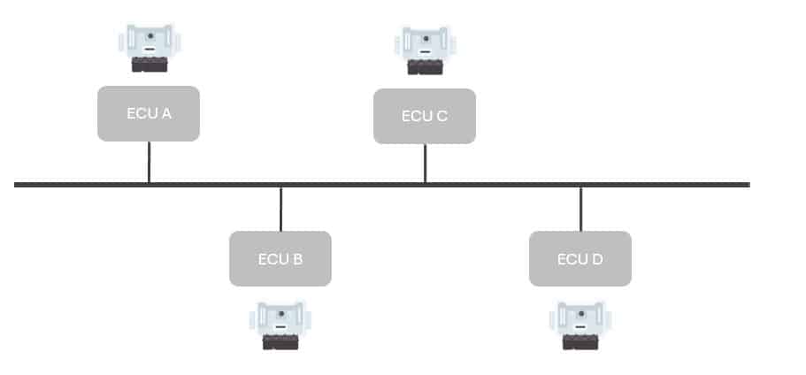
The CAN Bus protocol allows different Electronic Control Units (ECUs) in a vehicle to communicate with each other, enabling them to share data and perform critical tasks. This is crucial for vehicle operations, ensuring that systems like brakes, acceleration, and steering are properly controlled.
It is an asynchronous half-duplex communication protocol that allows nodes on the network to transmit and receive data. Here is a simplified overview of how it works:
- Nodes: Each node on the CAN bus is connected to the bus through a transceiver, which converts digital signals from the node into differential signals for transmission.
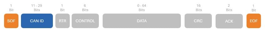
Message Structure: A message transmitted over the CAN bus consists of:
- Identifier (ID): a unique identifier that specifies the priority and destination of the message
- Data: the actual data being transmitted
Transmission: When a node wants to transmit a message, it sends its ID on the bus first. If no other node has an ID with higher priority, the transmitting node can then send its data.
Receiving: Nodes on the CAN bus continuously monitor the bus for messages. When a node detects an ID that matches its filter (based on priority and destination), it receives the message and checks the data for errors.
Error Handling: If a node detects an error in a received message, it will notify other nodes on the bus to prevent further transmission of faulty data.
Bus Arbitration: When multiple nodes want to transmit simultaneously, a priority scheme (deterministic or non-deterministic) is used to resolve conflicts and ensure only one node transmits at a time.
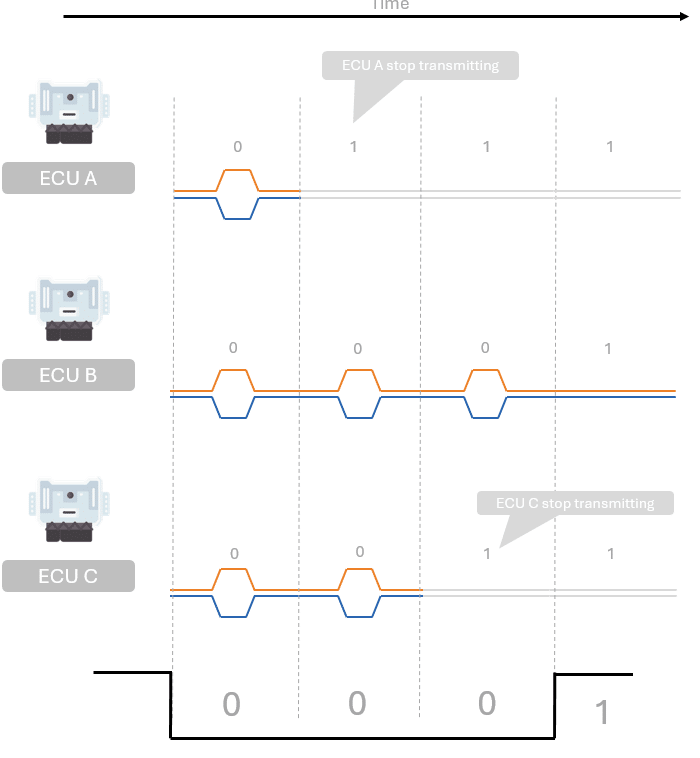
At a deeper level, this arbitration mechanism is attributed to the physical CAN (Controller Area Network) layer.
By default, every node on the bus assumes a recessive state, which represents a logical ‘1’.
When transmission occurs, the recessive state is overridden by the dominant bit, which represents a logical ‘0’.
This clever mechanism ensures that nodes with the lowest ID always have priority.
According to convention, when a node transmits a logical ‘1’, it continuously monitors the bus level to detect any dominant state. If no dominant state is detected, the transmitting node ceases transmission, thereby preventing collisions and ensuring reliable communication on the CAN bus.
The main difference between CAN HS and CAN FD lies in the data rate and flexibility they offer.
Classical CAN has a fixed maximum data rate of 1 Mbit/s, whereas CAN FD offers a flexible data rate that can go up to 8 Mbit/s, depending on the transceiver and bus configuration.
Additionally, CAN FD allows for more efficient transmission of larger payloads by using a new frame format and error detection mechanism.
Integration flipper Zero with Can Bus
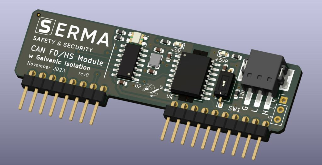
To integrate the Flipper Zero with the CAN Bus protocol, a CAN Bus adapter is needed. This adapter connects the Flipper Zero to the vehicle’s CAN Bus network, allowing it to read data from various sensors and ECUs. SERMA Safety & Security has developed such an adapter, leveraging the GPIO connectors of the Flipper Zero to plug in an extension board.
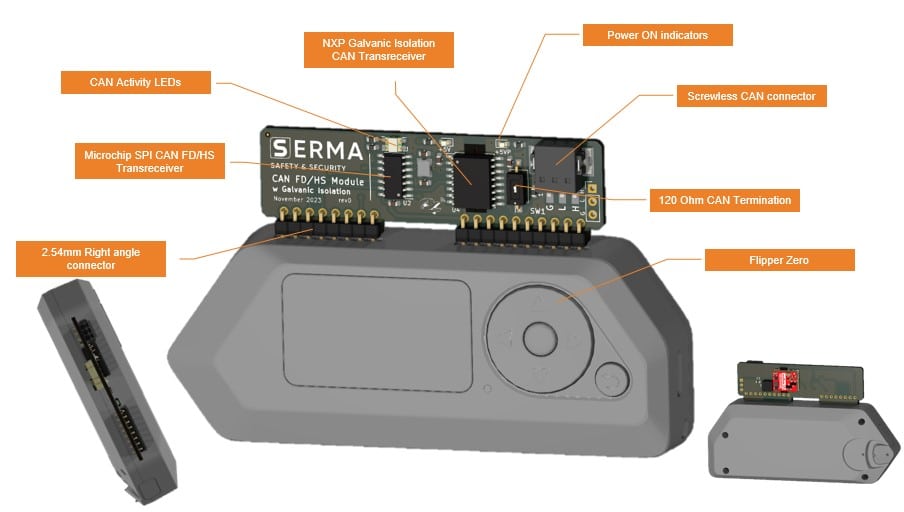
Using a Microchip MCP2518FD, the adapter enables the Flipper Zero to send CAN HS (CAN 2.0B) and CAN FD signals safely, thanks to galvanic isolation provided by the NXP TJA1051i transceiver. The board also includes a bi-color LED to monitor CAN bus activity and an onboard 120 Ohm termination resistor that can be toggled on and off. Additionally, a Phoenix Contact screwless CAN connector allows for quick and easy bus connections.
How it works?
To keep things simple, we have developed an initial version of an application that makes your Flipper Zero behave as a USB-CAN adapter.
Specifically, we have ported a SLCAN driver into the Flipper Zero, allowing it to work with pre-existing tools like can-utils. However, you will need a laptop or similar embedded system to send and receive CAN messages, as currently, only OSI Layers 1, 2 and 3 are provided by our solution.
For proper vehicle operation, upper OSI layers like Transport (CAN_ISO-TP), Presentation, and Application need to be handled externally.
At SERMA Safety & Security, we offer a wide range of ready-to-use Python scripts that enable interaction with ECUs using different CAN communication protocols, notably the UDS (Unified Diagnostic Services). UDS allows for diagnostics, firmware updates, routine testing, and more in automotive ECUs. In cars, UDS is used for various purposes, including:
- Reading and clearing diagnostic trouble codes (DTCs) for troubleshooting vehicle issues.
- Extracting parameter data values such as temperatures, state of charge, VIN, etc.
- Initiating diagnostic sessions to test safety-critical features.
- Modifying ECU behavior via resets, firmware flashing, and settings modification.
We will see in future blog post how we can use the Flipper Zero for this purpose.